Clive’s Corner #16: Photomicroscopy - Capturing the Primary Image
This installment of “The Corner” continues on the topic of taking photographs though a microscope and focuses on the primary image. This is the real image produced directly by the objective lens in the case of a finite tube-length microscope (Figure 1a), or by the tube lens in the case of an infinity-corrected microscope. In either case, the primary image is typically located 10 mm in from the end of the eyepiece tube. The simplest way to view and capture this image is to use a USB eyepiece camera where the sensor is positioned at the primary image plane and the image is observed directly on a computer screen (Figure 1b). Alternatively, adapters are available to attach the camera body of a digital SLR or mirrorless camera to the eyepiece tube (Figure 1c,d). These provide another cheap option, assuming you are already in position of such a camera**.
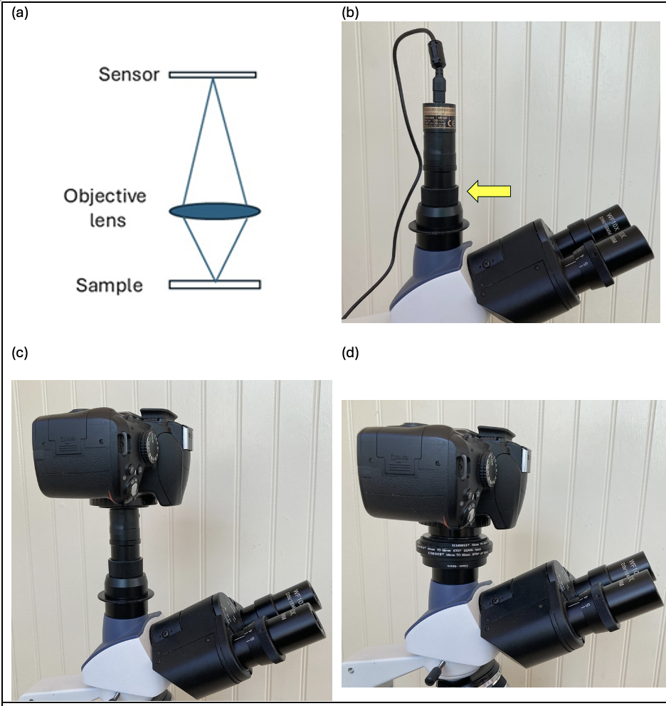
Figure 1. (a) A schematic showing the primary image formed by a microscope objective lens. (b) A USB eyepiece camera mounted in a trinocular port. The yellow arrow marks the adjustment collar to make the sensor parfocal with the eyepieces. (c) A digital SLR camera attached to the trinocular port using a 23.2 mm eyepiece adapter. (d) The same camera attached via a combination of stepping rings and a 42 mm T2 thread adapter.
Regardless of the camera type, it is desirable to mount the sensor at the correct height so that it is parfocal with the eyepiece. In the case of the USB eyepiece camera an adjustment collar is used to raise or lower the height of the camera (Figure 1b, yellow arrow). Not only does this make it convenient to switch between the eye and camera view, but the objective lens is designed to work at its optimal tube-length to minimize aberrations. USB cameras are small and light enough to fit into the eyepiece tubes of monocular or binocular microscopes without becoming top-heavy, but a trinocular microscope is more convenient in allowing simultaneous viewing by eye and camera,
Figure 2a shows a lens-less USB camera suitable for an eyepiece tube diameter of 23.2 mm and an adapter for 30.5 mm diameter eyepiece, typically found in stereo microscopes. This particular model has a sensor size of 3.6 x 2.8 mm and 1.3 Mpixel chip. The main disadvantage of this camera is the small chip size compared with the maximum diameter of the primary image, which is around 22 mm for my Amscope 120 and Swift 350 microscopes. The captured field-of-view is about 1/5 that seen through the supplied 10x eyepiece with a field number of 18 mm (Figure 1b). What does the latter mean? Well, as an example, when viewing an object 1.8 mm long with a 10x objective lens, the primary image would be 18 mm long and would just fit the eyepiece view, but the camera would only detect the central 3.6 mm of the image and thus the field-of-view would correspond to 0.36 mm of the object. While this is a limitation, there is some good news when economy is a priority. One of the major limitations of capturing the primary image is that the periphery of the image may not be very sharp, especially for 160 mm tube-length microscopes intended for the hobby market. Here, correction for chromatic and spherical aberration is achieved through the combined action of the objective lens with the supplied eyepiece lens. When the objective is used on its own, the image periphery will be blurred. By restricting the field-of-view to the central 1/5, the primary image is of acceptable quality. A similar argument applies to non-plan achromatic objectives, which have a curved field-of-view, so that the center and the edges of a flat specimen cannot be focused at the same time. This is not a problem when only the center of the image is captured, as with this lens-less USB camera. A restricted field-of-view also means that a 1.3 Mpixel sensor is sufficient to capture an image without incurring loss of detail because the resolution is limited by the wavelength of visible light for all but the lowest magnification objectives (see Pushing the limits). Fewer pixels allows higher frame rate for video recording. Table 1 summarizes the advantages and limitations of lens-less USB eyepiece cameras.
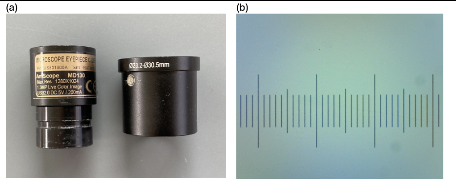
Figure 2. (a) A 1.3 MP USB lens-less camera designed to fit a 23.2 mm microscope eyepiece tube, together with an adapter to fit a 30.5 mm eyepiece tube. The latter was modified to include a small spigot so that the camera could be clamped into the eyepiece of a stereo microscope and prevent rotation within the barrel. (b) The full field-of-view of a 10 µm graticule captured with a 10x objective lens, corresponds to 0.36 mm (360 µm) compared with 1.8 mm seen by eye through a 10x eyepiece.
If a larger field-of-view is a priority, then USB eyepiece cameras are available with a built-in reduction lens (e.g. 0.5x or 0.3x), to project a smaller version of the primary image onto the camera chip. However, unless this lens happens to provide the necessary correction for chromatic and spherical aberration for the specific microscope objective brand, then the periphery of the image may not be of acceptable quality. Furthermore, more pixels will be required to prevent this factor limiting the resolution.

Table 1.
The small-sensor problem of USB cameras can be overcome by using the camera body of an SLR (single lens reflex) or mirrorless camera designed for regular photography. Full-frame cameras based on the 35 mm format have the opposite problem because now the sensor (36 x 24 mm) is larger than the primary image, meaning some of the sensor is wasted. Additional lenses may be used to better match the image and sensor size (e.g. 2x lens). Cameras with APS-C sensors (~ 23 x 15 mm) or 4/3 sensors (17 x 13 mm) are a better match to the primary image size and can be used without any additional lenses. Additional lenses may still be employed however, so that the camera rectangular image just fits within the circular primary image without shading in the corners. Here the challenge is to find a way to mount the camera on the microscope. In the case of upright microscopes, these cameras are best used with a trinocular head since they may become top-heavy when attached to an angled eyepiece tube.
Eyepiece adapters are available for coupling Nikon and Canon camera bayonet mounts to 23.2 mm eyepiece tubes, with or without intermediary lenses. These adapters comprise two parts: a 23.2 mm tube (which may contain magnifying lenses) attached to a male T2 thread and a female T2 thread joined to the camera specific bayonet mount (Figures 3a,b). T2 threads (42 mm diameter, 0.75 mm pitch) are widely used for camera and telescope mounts and are useful for assembling custom devices. For example, a bayonet mount -T2 adapter for another brand of camera can be combined with the T2-23.2 mm tube adapter part to attach the camera to the eyepiece tube of the microscope. A limitation of the lens-less eyepiece adapter is that there is insufficient adjustment of the eyepiece tube to make the camera and eyepieces parfocal. The camera sensor is further away from the eyepiece primary image plane (Figure 1c cf. 1b) and the microscope requires slight refocusing to bring the camera image into focus. This problem can be solved using a custom-built adapter assembled from camera filter stepping rings (Figure 1d) but there still remains a limitation of this approach.
Adapters without an intermediary lens may capture a large field-of-view but, in the case of a 160 mm tube-length microscope, the image will likely be blurred at its periphery and may incur vignetting (Figures 3c,e,f). Using a 2x lens in the adapter restricts the field-of-view (but not as much as a lens-less USB camera - cf. Figures 3d,g,h with Figure 2b) and may correct for some of the objective lens aberrations. However, the degree of correction required varies between brands and so no single adapter will be optimal for all microscope objectives. Infinity-corrected objectives are used in conjunction with an in-built tube lens within the microscope body which can contribute to aberration correction and so the primary image will likely be sharper across the whole field-of-view.
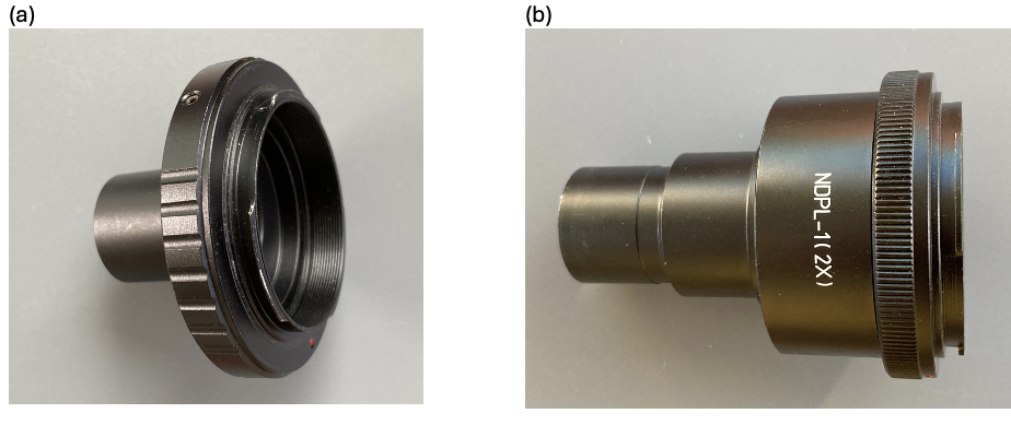

Figure 3. (a) Lens-less 23.2 mm tube adapter for Nikon camera (b) Similar adapter but with built-in 2X lens. (c)-(g) 10 µm graticule imaged with a 10x achromat objective lens. (c) Field-of-view with lens-less adapter equals 1.9 mm but is not parfocal with eyepiece. (d) Field-of-view with 2x adapter equals 0.75 mm. (e-f) Enlarged view of image c showing (e) center and (f) edge of field. (g-h) Enlarged view of image d showing (g) center and (h) edge of field. Note that for the wide field image of (c) but over a limited field equivalent to (d), the image quality is closer to that in (e) than (f).
Apart from the challenges of mounting a regular camera on a microscope, there is also a need for external triggering of the shutter. Pressing the button on camera is likely to cause some camera movement, especially when exposure times are longer than 1/100th of a second. Setting the shutter to delay mode helps prevent camera movement during the capture, but the mirror movement of dSLRs may still cause some problems. In this regard, mirrorless cameras have an advantage. Digital cameras often come with software for remote control. The free app, digiCamControl allows control of many Nikon, Canon and Sony digital cameras and, in some cases, enables Live-view. The latter allows review of the image on a computer screen or separate monitor before activating the shutter or recording a video and is particularly valuable for fine focusing of the subject. The images/video may be directly recorded on a computer as well as any storage card within the camera. Cameras that have an HDMI output can be viewed directly on a monitor or TV screen or connected to a USB port of a computer using an adapter.
It is evident from Figure 3c, that the 23.2 mm tube of the lens-less adapter clips the image in the corners (i.e. vignetting). This problem can be overcome using an alternative adapter with a wider diameter tube. A custom-built adapter can be made from a bayonet-T2 adapter in combination with some camera filter stepping rings and a M42-T2 adapter. A 52 mm diameter male threaded ring is sandwiched between the head pieces of the trinocular port and the tube built up with the other rings to be the correct height for the camera to be near parfocal with the eyepieces (Figure 1d). This reveals an even larger field-of-view (field number = 22) than seen through the 10x eyepiece, but the image quality is very poor at the edges (Figure 4a,d). This is in part due to a curved field-of-view, as is evident by focusing on the edges of the field which results in an out-of-focus central region. Using a plan achromat objective reduces this problem (Figure 4b, e-f), but aberrations are still apparent in the periphery.

Figure 4. (a) Primary image of 10 µm graticule captured with a 10x achromat objective (160/0.17) using a dSLR camera attached to an Amscope 120 microscope via 42 mm adapter as shown in Figure 1d. (b) Similar set-up but with 10x plan achromat objective (160/0.17). (c) Center and (d) edge of the image shown in (a). (e) Center and (f) edge of the image shown in (b).
Table 2 summarizes the advantages and disadvantages of using full frame cameras.

Table 2.
Infinity-corrected objectives, as found on most research-grade microscopes, fare better in producing sharp primary images across the whole field, partly because they are likely to have better quality optics in general, but also because the tube lens may contribute to aberration correction of the objective lens. Figure 5 shows the same graticule imaged with an Optika 510 microscope and Lumix mirrorless camera attached via a camera specific adapter.

Figure 5 (a) A Lumix GX85 mirrorless camera attached to an infinity tube-length Optika B510 microscope (inset = 10x objective lens). (b) 10 um graticule imaged with a 10x infinity objective shows a field-of-view of 1.74 mm i.e. the primary image was 17.4 mm diameter. Enlarge sections from the (c) center and (d) edge of field.
Is it possible to capture a large field-of-view and sharp focus across the field with an economy finite tube-length microscope? A possible solution using a modified form of the afocal method with a wide-field eyepiece will feature in the next installment of the corner. However, for routine monitoring of plankton, I find the 1.3 MP USB camera with its small field-of-view is sufficient (Figure 1b). Plankton can be located by eye in the larger field-of-view and quickly centered and photographed using the USB camera without wasting pixels (and keeping file sizes small).
**Footnote: The reference to infinity-corrected microscopes and mirrorless cameras may seem a bit out of context for a typical budget-conscious Corner article. I would like to thank Bob Carey for donating his Optika microscope and Lumix camera to enable this comparison and more.